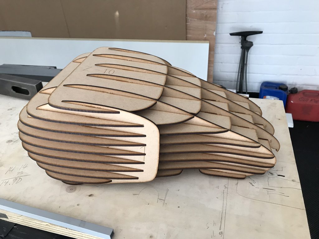
Prototyping Large Parts: A friend of ours is a sculptor. He creates the initial shapes for his sculptures by carving into blocks of balsa wood. This method is very skilled and tactile and allows him to see, and feel, the contours, size and scale as he goes. We’re less skilled at this approach and tend to use sketches and CAD to create the initial form of a design. Although there are various electronic aids (e.g. CAD, photo editing, drawing, tracing, etc) to design something there’s nothing quite like having the part in your hands. Designs on a screen can be difficult to imagine in the real world, particularly when a design is part of a bigger assembly.
A common method in the automotive industry is to create a clay model, either full size or to scale. Although we have dabbled in clay modelling, our abilities don’t extend to this very skilled practice.
One very effective way of taking a design in CAD and creating a physical equivalent or prototype is to break the part down into horizontal and vertical slices. This is especially true for large, bulky shapes like a fuel tank on a motorcycle. This is somewhat similar to the lofting technique used by traditional boat builders.
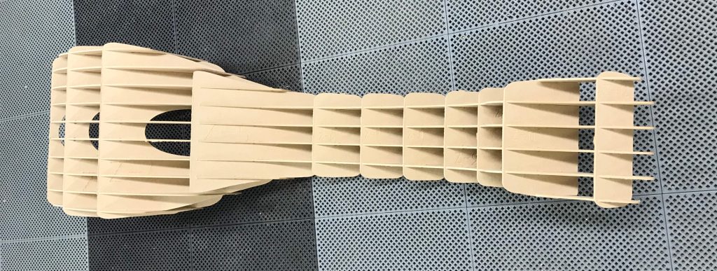
Once the design has been created in CAD, the solid object is sliced using a ‘slicer’ utility – some CAD packages have this feature built in or specialist packages are available. The number of vertical Vs horizontal slices depends on the complexity of shape being created. Shapes with lots of compound curved surfaces typically require more slices. Assembly of the slices can be more difficult the more slices there are. As a general rule, we create as few slices as possible in both dimensions that create a true to life finished prototype.
Once sliced, each slice profile can be cut (e.g. laser, water, CNC milled, etc) from thin sheet material – typically 3-4 mm but it depends on what is available, size of the design, cutting method, etc. MDF works quite well, so too does plywood but there are other options. Depending on the slicer software used, each slice is labelled to aid assembly.
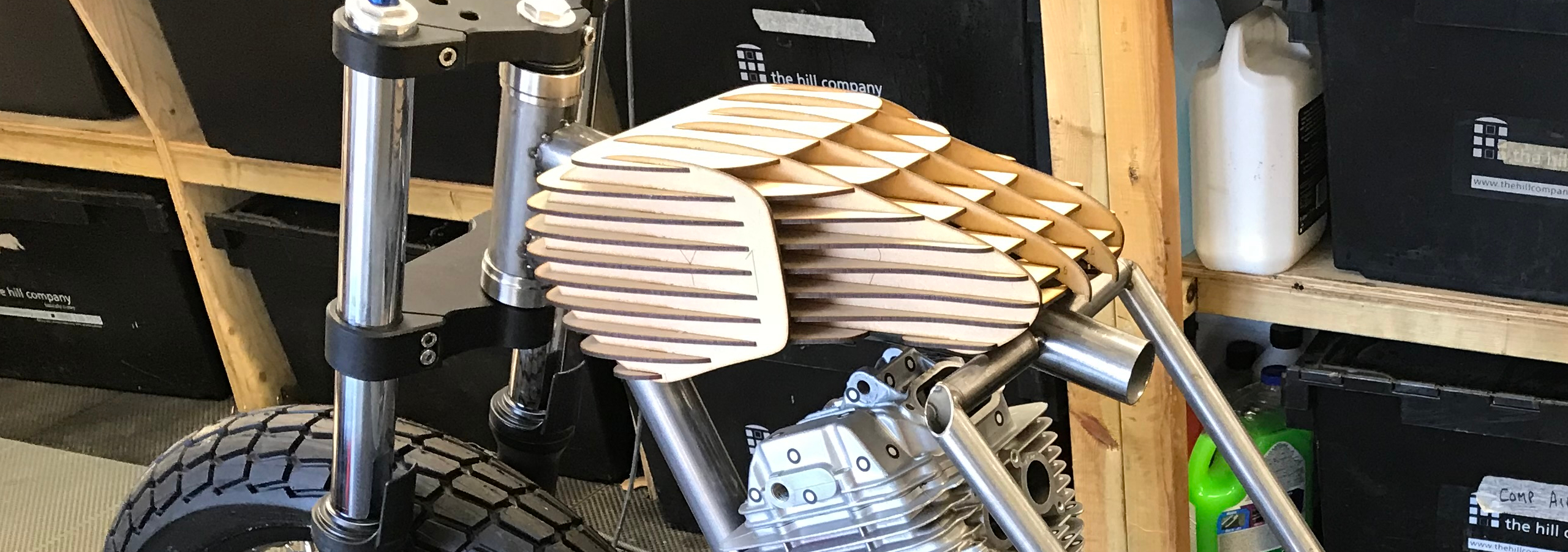
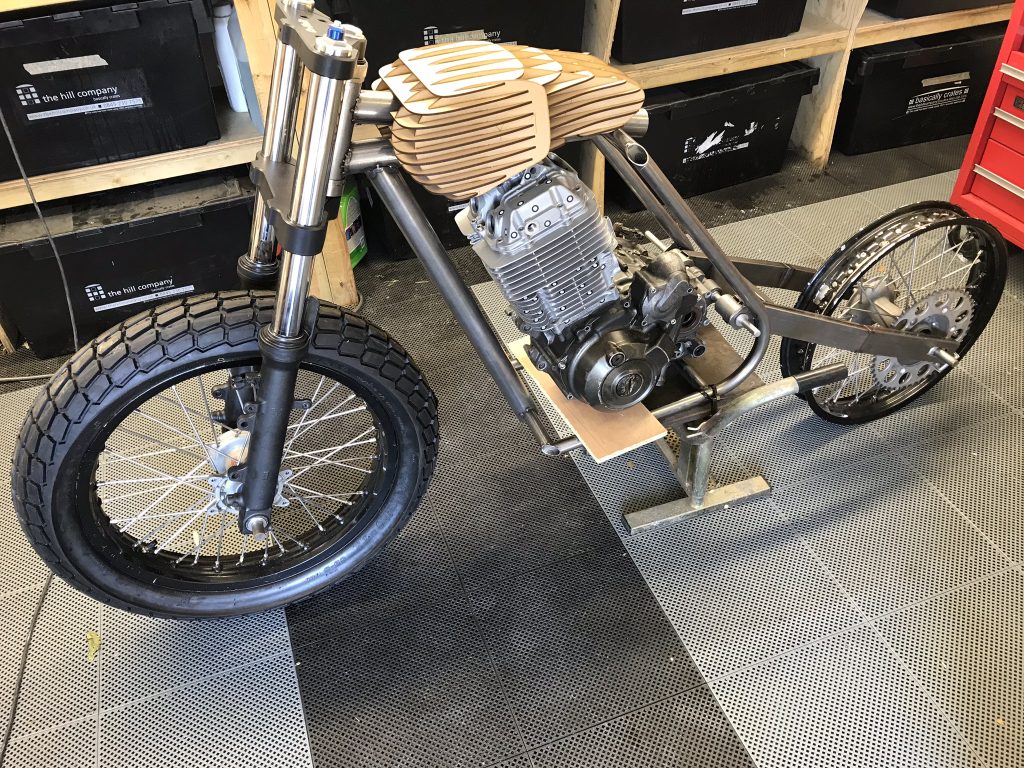
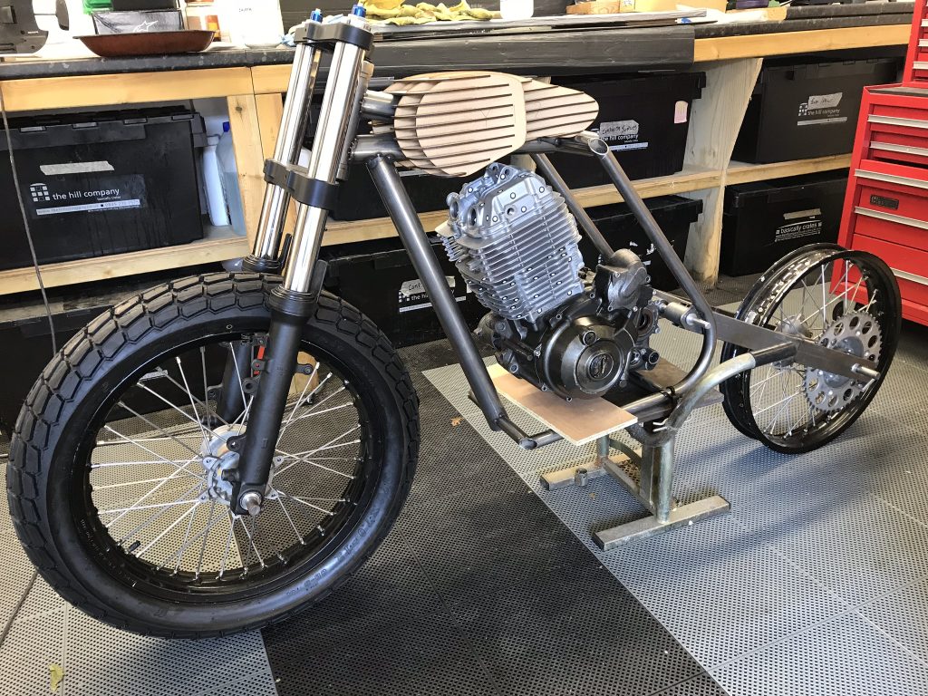
The slices have interlocking grooves cut that are used to slide the slices together. Once fully assembled, the prototype can be used to check size, scale, shape, fitment, packaging, etc in relation to surrounding parts.
The fuel tank shown in the pictures below looked fine on screen but turned out to be a little too small in reality. A small tank looks great but would be impractical on the road – maybe fine for short flat track races though. We liked the shape but will scale slightly bigger in CAD, slice, cut, assemble and try again for size.
Additive manufacturing (3D printing) could of course be used however this can be inefficient and wasteful on bigger parts. The suggestion here is not that the ‘slicer’ method is the only or best approach but the outcomes can be very effective. The slicer method allows for quite large parts to be prototyped whilst minimising material use, cost and time.
We have also used the sliced prototypes to create a plug, or master part, from which moulds can be taken. These moulds have been used to make carbon fibre parts. The plan for this flat track framer build is to design and manufacture the tank and sent unit ourselves, probably using carbon fibre.
